 |
The purpose
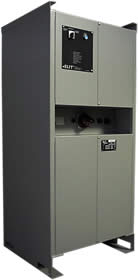
of the converter is to provide an alternating sinusoidal
stabilized voltage with a low harmonic distortion, at
400Vac 50Hz.
The converter is composed by a three phase IGBT inverter
fed directly by the 3kVdc voltage.
MAIN
COMPONENTS:
1)
Input filter. It has the following functions:
- reducing the input surge at the converter;
- reducing the input voltage harmonic distortion in
order not to disturb the signalling circuits;
The input contactor, with the relative ground equipment,
has to be installed outside.
2)
24Vdc auxiliary battery voltage power supply:
It provides two stabilized voltage to +12 –12Vdc
to supply the control logic and a alternating voltage
70V-40kHz to supply inverter driver cards.
3)
Control logic:
It provides the control signals to the inverter driver
cards, in order to supply a three phase alternating
sinusoidal and stabilized voltage in all conditions,
with load variations and with voltage sags. The control
logic assures all operations regarding the start up
and shutdown procedures and protection of the apparatus
against input overvoltage and output overload. |
|
4)
Inverter bridge:
It is composed by a IGBT Greatz bridge type with PWM three-phase
regulation with a frequency modulation of 600Hz: this value
optimes the invert losses and meanwhile it gets a good output
waveform. The insulation between the control logic and the
drivers is obtained with optical cables.
5) Transformer
and filter capacitor:
The output voltage of the bridge is an PWM alternating voltage
at three steps. The transformer fits the value of the bridge
output voltage at the value of the converter output voltage
creates the input/output insulation and realizes the inductive
part of the output filter. The output filter reduces the
harmonic content of the output and limits voltage deviations
under step load conditions.
6) Output
converter unit:
The converter is configurated for both three phase and single
phase outputs. To protect the users, two output circuit
breakers are configured. The converter is provided by a
by-pass switch which allows to feed the output from an external
mains at 400Vac 50Hz (service point) when the coach is in
maintenance.
|
INPUT PARAMETERS (dc
voltage)
|
| •
Input voltage [Un]: 3000V |
| •
Minimum continuos voltage [Umin1]: 2000V |
| •
Minimum voltage for 10 minutes [Umin2]: 1800V |
| •
Maximum continuos voltage [Umax1]: 3600V |
| •
Maximum voltage for 5 minutes [Umax2]: 3900V |
| •
Maximum inrush voltage: 4050V |
| •
Input overvoltage: |
| |
- 14kV per 1msec. [Umax4]
- 5075V per 20msec. [Umax3]
- 4050V per 2sec. [Umax2A] |
| •
Test atmospheric pulse voltage (EN 50124-1): 18kV |
|
|
OUTPUT PARAMETERS
|
| •
Output voltage: 400Vac 3Ph+N |
| •
Continuos output current: 60 A |
| •
Overload: |
| |
125% per 10 minuti
200% per 1 minuto |
| •
Static stability: +-5% |
| •
Output frequency: 50Hz +-1% |
| •
Phase voltage symmetry: 120°+-1°. |
| •
Voltage harmonic distortion (THD) at linear load:
5% |
| •
Maximum dynamic stability: +-10% |
| •
Recovery time: 40msec. |
| •
Insulation resistance at 1000Vdc: up to 10Mohm |
| •
Dc input and output dielectric strenght: 12000V,
50Hz for 60 sec. |
| •
Efficiency: > 86% |
| •
Noise level: less than 70dBA |
| •
Maximum insertion time: 15 sec. (programmable) |
|
|
PROTECTIONS
• Overvoltage
• Internal hight temperature
• Overload
• Short circuit
• Soft start
|
ENVIRONMENT CHARACTERISTCS
|
•
Operating temperature: -25 / + 50°C
• Maximum relative
humidity: 95% (condensing)
• Maximum Altitude:
1400 meters
• Dust granulemeters
(variable composition with the presence of metallic
granules ): |
| |
From 80 to 200um:
10% in weight
From 0 to 80um: 90% in weight |
•
Pushes or vibrations: according to IEC 61373
• Protection
class: IP 22 |
|
|
SYSTEM PARAMETERS
|
| •
Dimensions: |
|
| |
Width = 800mm
Depth/length = 750mm
Heigth = 1805mm |
| •
Weight: 450kg |
| •
Bottom and top fastening. |
| •
Access for maintenance and repairs: front. |
| •
Interruttori e spine accessibili ad armadio chiuso. |
| •
Cabinet in sheet-iron witth sintetic furnance
painting. |
| •
Color: grey RAL 7001 |
|
|
EMC - Electromagnetic Compatibility
D.L. 615/96 (conform to the following directives: 89/336/EEC,
92/31/EEC, 93/68/EEC and 93/97/EEC
|
ELECTRICAL CONNECTIONS
• Input line 3000Vdc: M8
screw
• Battery: connector
• 380V output: connector
• 220V output: connector
• Input service tap: connector
|
LOCAL CONTROLS
switch at three positions 1-0-2
• pos.1: CONNECTED
• pos.0: OFF
• pos.2: PREDISPOSITION
TO REMOTE CONNECTION |
SIGNALLING
• battery input : ok
• 3000Vdc input: 0k
• 380V output: 0k
• 220V output: ok
• fault |
| download
pdf |
 |
ask
for a quotation |
 |
|